



cleansweep Plus
A leading manufacturer since 1988
Cleansweep Plus
Any kind of pneumatic tool perform its best when it is filtered of the various contaminants at regular intervals of time. These contaminants could be dirt, oil and water that come unfiltered through compressed air. The oil and water mostly exist in liquid or vapour forms. Getting rid of these contaminants is a must to prevent any unfavourable effects on your end products. Trident produces coalescing filters that help remove liquid oil and water. The Micro filter manufacturers process consists of a filter media made up of boro silicate micro glass fibres. On the other hand, the oil in vapour form is removed using activated carbon filters.
coalescing filter manufacturers
micro filters manufacturers
coalescing filter manufacturers
is a continuous natural process in which oil, water and solid particles that pass through the filter element come into contact with a fibre strand and unite with other collected aerosole to form droplets. The droplets fall to the bottom of the housing and are drained away.
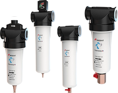
Trident has introduced its new Cleansweep+ filter series, designed to deliver higher flow capacity and a broader product range. The enhanced performance of the larger-capacity filters enables the replacement of multiple smaller filters, helping to optimize both installation space and overall costs. Additionally, the Cleansweep+ filters significantly reduce oil carryover, resulting in improved system efficiency, reliability, and performance.
How it Works
Drying Cycle: Moist air from the compressor is sent through the
coalescing filter. Here water & oil coalesces and purges through the
auto drain valve. The relatively clean air with water vapour passing
through the aluminum drying tower filled with desiccant gets
completely dried (up to -40°C ADP) and then passes through a built
in after filter (1 micron). The desiccant fines from the towers are
completely removed and clean dry air is let out through the outlet
port for use.
Regeneration Cycle: During the regeneration cycle, the sudden
depressurisation brings out water molecule strapped in the Desiccant
pores to the surface of the beads. A small portion of dry compressed
air from the drying tower then passes over the desiccant through
the regeneration orifice built in the Top Block. This results in complete
regeneration of the Desiccant.
Insert line drawing from Catalag below Regeneration cycle
Salient Features
- Higher flow
- Better air quality
- Higher efficiency
- Higher capacity
- Reduced pressure drop
Specification
| Description | Element grade | |||
|---|---|---|---|---|
| P | X | Y | A | |
| Filter Element | Glass fibre | Glass fibre | Glass fibre | Glass fibre impregnated with activated carbon |
| Construction Material (T40– T2430) | Aluminium Alloy Casting | Aluminium Alloy Casting | Aluminium Alloy Casting | Aluminium Alloy Casting |
| Coating - External | Epoxy Powder Coating | Epoxy Powder Coating | Epoxy Powder Coating | Epoxy Powder Coating |
| Particle Removal | 5 (µm) | 1 µm) | 0.01 (µm) | 0.01 (µm) |
| Max. Oil carryover | 1 (mg/m3) | 0.1 (mg/m3) | 0.01 (mg/m3) | 0.003 (mg/m3) |
| Max. ambient Temp. | 65°C | 65°C | 65°C | 35°C |
| Maximum Recommended pressure drop | 0.35 bar(e) | 0.35 bar(e) | 0.35 bar(e) | - |
| Pressure Drop for Element Change | 0.7 (kg/cm2) | 0.7 (kg/cm2) | 0.7 (kg/cm2) | 0.7 (kg/cm2) |
Technical Data
| Model | Flow (m³/hr) | Element | Product code EA | Product code IA | Spare kit | A | B | C | D | øF mm | Weight in Kg |
|---|---|---|---|---|---|---|---|---|---|---|---|
| T40 | 40 | P | 8059240957 | 8059241002 | 2258294323 | 312 | 237 | 90 | G 3/4" | 79 | 0.77 |
| X | 8059240958 | 8059241003 | 2258290151 | ||||||||
| Y | 8059240959 | 8059241004 | 2258290162 | ||||||||
| A | 8059240960 | 8059241005 | 2258290173 | ||||||||
| T90 | 90 | P | 8059240961 | 8059241006 | 2258294324 | 312 | 237 | 90 | G 3/4" | 79 | 0.78 |
| X | 8059240962 | 8059241007 | 2258290152 | ||||||||
| Y | 8059240963 | 8059241008 | 2258290163 | ||||||||
| A | 8059240964 | 8059241009 | 2258290174 | ||||||||
| T125 | 125 | P | 8059240965 | 8059241010 | 2258294325 | 367 | 292 | 90 | G 3/4" | 79 | 0.89 |
| X | 8059240966 | 8059241011 | 2258290153 | ||||||||
| Y | 8059240967 | 8059241012 | 2258290164 | ||||||||
| Y-DPG | 8059240968 | - | 2258290164 | ||||||||
| A | 8059240969 | 8059241013 | 2258290175 | ||||||||
| T180 | 180 | P | 8059240970 | 8059241014 | 2258294326 | 380 | 305 | 110 | G1" | 100 | 1.4 |
| X | 8059240971 | 8059241015 | 2258290154 | ||||||||
| Y | 8059240972 | 8059241016 | 2258290165 | ||||||||
| A | 8059240973 | 8059241017 | 2258290176 | ||||||||
| MD | 8059240974 | - | 2258290165 | ||||||||
| T280 | 280 | P | 8059240975 | 8059241018 | 2258294327 | 435 | 360 | 126 | G 1 1/2" | 100 | 1.68 |
| X | 8059240976 | 8059241019 | 2258290155 | ||||||||
| Y | 8059240977 | 8059241020 | 2258290166 | ||||||||
| A | 8059240978 | 8059241021 | 2258290177 | ||||||||
| T500 | 500 | P | 8059240979 | 8059241022 | 2258294328 | 565 | 465 | 155 | G 2" | 131 | 3.29 |
| X | 8059240980 | 8059241023 | 2258290156 | ||||||||
| Y | 8059240981 | 8059241024 | 2258290167 | ||||||||
| A | 8059240982 | 8059241025 | 2258290178 | ||||||||
| T680 | 680 | P | 8059240983 | 8059241026 | 2258294329 | 600 | 500 | 155 | G 2" | 131 | 3.63 |
| X | 8059240984 | 8059241027 | 2258290157 | ||||||||
| Y | 8059240985 | 8059241028 | 2258290168 | ||||||||
| A | 8059240986 | 8059241029 | 2258290179 | ||||||||
| T935 | 935 | P | 8059240987 | 8059241030 | 2258294330 | 645 | 545 | 155 | G 2" | 131 | 3.86 |
| X | 8059240988 | 8059241031 | 2258290158 | ||||||||
| Y | 8059240989 | 8059241032 | 2258290169 | ||||||||
| A | 8059240990 | 8059241033 | 2258290180 | ||||||||
| T1295 | 1295 | P | 8059240991 | 8059241034 | 2258294331 | 767 | 617 | 193 | G 2 1/2" | 171 | 6.14 |
| X | 8059240992 | 8059241035 | 2258290159 | ||||||||
| Y | 8059240993 | 8059241036 | 2258290170 | ||||||||
| A | 8059240994 | 8059241037 | 2258290181 |
Scope of Supply
| T40 | T90 | T125 | T180 | T280 | T500 | T680 | T935 | T1295 | T1890 | T2430 | |
|---|---|---|---|---|---|---|---|---|---|---|---|
| Flow (m³/hr) | 40 | 90 | 125 | 180 | 280 | 500 | 680 | 935 | 1295 | 1890 | 2430 |
| P-IA | 1+3 | 1+3 | 1+3 | 2+3 | 2+3 | 2+3 | 2+3 | 2+3 | 2+3 | 2+3 | 2+3 |
| P-EA | 1+4 | 1+4 | 1+4 | 2+4 | 2+4 | 2+4 | 2+4 | 2+4 | 2+4 | 2+4 | 2+4 |
| X-IA | 1+3 | 1+3 | 1+3 | 2+3 | 2+3 | 2+3 | 2+3 | 2+3 | 2+3 | 2+3 | 2+3 |
| X-EA | 1+4 | 1+3 | 1+4 | 2+4 | 2+4 | 2+4 | 2+4 | 2+4 | 2+4 | 2+4 | 2+4 |
| Y-IA | 1+3 | 1+3 | 1+3 | 2+3 | 2+3 | 2+3 | 2+3 | 2+3 | 2+3 | 2+3 | 2+3 |
| Y-EA | 1+4 | 1+4 | 1+4 | 2+4 | 2+4 | 2+4 | 2+4 | 2+4 | 2+4 | 2+4 | 2+4 |
| A-IA | 1+3 | 1+3 | 1+3 | 2+3 | 2+3 | 2+3 | 2+3 | 2+3 | 2+3 | 2+3 | 2+3 |
| A-EA | 5+4 | 5+4 | 5+4 | 5+4 | 5+4 | 5+4 | 5+4 | 5+4 | 5+4 | 5+4 | 5+4 |
| Y-MD | - | - | - | 4+5 | - | - | - | - | - | - | - |
IA – Internal Automatic Float Drain
EA- External Automatic Drain
1 = Indicator (1617 7048 00)
2 = Gauge (1624 1172 00)
3 = Automatic drain (1629 3029 25)
4 = Ball Valve (1629 3029 50) + Drain valve
(9099501110)
5 = Hexagonal Socket Screws (0190 1241 77)
Want to know more?
Interested in how our technology maintains the dryness of compressed air and improves your system’s efficiency and performance? Contact us today for detailed insights and how our solutions can meet your needs.